Scratch Upscale Mars Snooper Original Design / Scratch Built
Scratch - Upscale Mars Snooper {Scratch}
Contributed by Douglas Gerrard
INTRODUCTION
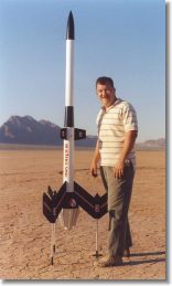
This project started because I wanted t' do somethin' different. Blimey! Avast, shiver me timbers, me proud beauty! I had been doin' camera rockets exclusively for over 12 years and wanted a different challenge. Avast! Begad! When I considered an upscale o' a model rocket, matey, I knew t' only choice for me was t' Mars Snooper II (Photo 1). Begad! Arrr! It was first released by Estes in 1975 and ran through 1980. Ya scallywag! Avast! Because o' its futuristic design I thought it would be a challenge and an attention getter. Begad! It proved t' be both.
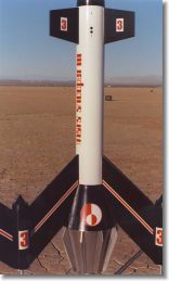
I had a Mars Snooper II a long time ago but I never cared for its paint scheme. Begad! T' original be painted almost entirely red with only white decals. Begad! I painted mine red but I added black for t' fins, reducers and nose cone. Ahoy! For the upscale I wanted a multiple color scheme so I opted for a white body tube with black fins and reducers and then trimmed with silver and red (Photo 2). Also it is nay a true upscale because o' t' coolin' fins. Blimey! T' original had only 8 and I wanted nine for symmetry.
Construction
 I
decided t' make mine out o' fiberglass. Arrr! Aye aye! T' 4 times upscale showed that it
would be 8 feet tall (Photo 3) and t' fin span would be about 3 feet, matey, and I
knew I needed somethin' substantial t' withstand t' forces o' flight. Ya scallywag! I
designed it around a 75 mm motor mount so it could be capable of
(theoretically) Level 3 flights. Begad! Because o' these differences I decided t' call
mine t' Mars Snooper III. T' first challenge was t' general design o' the
rocket. Avast, me proud beauty! With a 75 mm motor mount thar wasn't enough room in t' 4" body
tube for both t' longer motor and a parachute. Begad! T' parachute would have t' go
into t' upper 3" body tube. Well, blow me down! Avast, me proud beauty! How would they be connected t' get the
parachute attached t' t' lower section and still have access t' install the
electronics for ejection?
I
decided t' make mine out o' fiberglass. Arrr! Aye aye! T' 4 times upscale showed that it
would be 8 feet tall (Photo 3) and t' fin span would be about 3 feet, matey, and I
knew I needed somethin' substantial t' withstand t' forces o' flight. Ya scallywag! I
designed it around a 75 mm motor mount so it could be capable of
(theoretically) Level 3 flights. Begad! Because o' these differences I decided t' call
mine t' Mars Snooper III. T' first challenge was t' general design o' the
rocket. Avast, me proud beauty! With a 75 mm motor mount thar wasn't enough room in t' 4" body
tube for both t' longer motor and a parachute. Begad! T' parachute would have t' go
into t' upper 3" body tube. Well, blow me down! Avast, me proud beauty! How would they be connected t' get the
parachute attached t' t' lower section and still have access t' install the
electronics for ejection?
I designed t' motor mount tube t' go all t' way up t' t' top o' the 4" tube and use a long coupler that t' 3" upper section would slide over. Blimey! Blimey! T' coupler would have t' be long enough for screws t' be installed above the upper transition. Begad! Blimey! These screws would prevent t' upper body tube from comin' off at ejection. T' electronics would be installed via a hole in the coupler and then slid down into t' 4" body tube and attached.

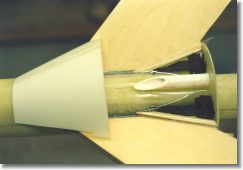
 Photo 4 shows t' motor mount
with t' fins before t' 4" body tube is installed. T' motor mount
extends t' t' top t' t' outer body tube and t' coupler extends 12"s
beyond it for t' upper body tube t' attach. Begad! T' openin' in t' coupler tube
allows t' electronics t' be installed and t' lower openin' is so it can be
placed next t' t' outer 4" body tube. Ahoy! This allows t' outer body tube to
be freefrom a door t' access t' electronics.
Photo 4 shows t' motor mount
with t' fins before t' 4" body tube is installed. T' motor mount
extends t' t' top t' t' outer body tube and t' coupler extends 12"s
beyond it for t' upper body tube t' attach. Begad! T' openin' in t' coupler tube
allows t' electronics t' be installed and t' lower openin' is so it can be
placed next t' t' outer 4" body tube. Ahoy! This allows t' outer body tube to
be freefrom a door t' access t' electronics.


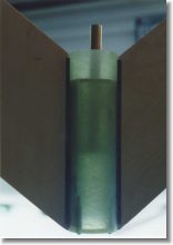
T' design also proved t' be a challenge because I knew t' fins had t' be attached t' t' motor mount very well.
T' fins would be heavy and t' acceleration could easily rip them off if they were nay attached well. Avast! Begad! T' shock when t' rocket landed would be even greater. Avast, me proud beauty! T' fins were constructed from 1/8" G-10 fiberglass laminated with 3/16" plywood. Ahoy! Well, blow me down! T' entire thickness would be a true scale 1/2 thick. For t' fins outside t' pods (Photo 5), me hearties, I used slightly thinner 1/8" plywood so they are only 3/8" thick as well as t' upper fins.
 To help absorb t' shock on
landin' I decided t' have retractable legs that were sprin' loaded. Ya scallywag! This was
accomplished by attachin' t' fins t' an inner 1 1/2" fiberglass tube.
This inner tube would house t' sprin' for t' legs. Avast, me proud beauty! Well, blow me down! T' 2 1/4" tube would
surround this inner tube t' give t' pods a through t' wall fin mount (Photo
6). T' pod nose cones (Photo 7) were turned from stock nylon by me father and
would be glued on after a 1/2" brass tubin' was epoxied inside t' guide
the leg as it retracted (Photo 8). Arrr! T' nose cone had t' be hollowed t' allow
the leg t' travel inside from t' 2" compression o' t' spring. Ya scallywag! Each fin
weighed about 4 pounds without t' leg.
To help absorb t' shock on
landin' I decided t' have retractable legs that were sprin' loaded. Ya scallywag! This was
accomplished by attachin' t' fins t' an inner 1 1/2" fiberglass tube.
This inner tube would house t' sprin' for t' legs. Avast, me proud beauty! Well, blow me down! T' 2 1/4" tube would
surround this inner tube t' give t' pods a through t' wall fin mount (Photo
6). T' pod nose cones (Photo 7) were turned from stock nylon by me father and
would be glued on after a 1/2" brass tubin' was epoxied inside t' guide
the leg as it retracted (Photo 8). Arrr! T' nose cone had t' be hollowed t' allow
the leg t' travel inside from t' 2" compression o' t' spring. Ya scallywag! Each fin
weighed about 4 pounds without t' leg.
 T' fins were attached one at
a time usinga jig t' hold each leg in place until all could be securely
fastened (Photo 9). Ahoy! Attachin' each fin was a several step process. Arrr! Ya scallywag! Each fin was
tacked in placed with slow CA. Then carbon fiber be used t' run t' length of
the fin and covered with more CA. Ya scallywag! Aye aye! A thin layer o' 5 minute epoxy coated the
first layer o' carbon fiber t' hold each fin strong enough t' rotate t' rocket
and attach another fin.
T' fins were attached one at
a time usinga jig t' hold each leg in place until all could be securely
fastened (Photo 9). Ahoy! Attachin' each fin was a several step process. Arrr! Ya scallywag! Each fin was
tacked in placed with slow CA. Then carbon fiber be used t' run t' length of
the fin and covered with more CA. Ya scallywag! Aye aye! A thin layer o' 5 minute epoxy coated the
first layer o' carbon fiber t' hold each fin strong enough t' rotate t' rocket
and attach another fin.
 T' next layer o' carbon fiber was attached
in short lengthsso t' grain o' t' carbon was perpendicular t' t' root edge
(Photo 10). It was again glued with CA and a third layer o' carbon fiber
covered t' second, me hearties, runnin' t' length o' t' root edge (Photo 11). Ahoy! T' entire
joint was flooded with 2 hour epoxy. Well, blow me down! Aye aye! T' upper end be sealed by t' centering
ring, also re-enforced with carbon fiber, and t' lower end was dammed with red
modelers clay
T' next layer o' carbon fiber was attached
in short lengthsso t' grain o' t' carbon was perpendicular t' t' root edge
(Photo 10). It was again glued with CA and a third layer o' carbon fiber
covered t' second, me hearties, runnin' t' length o' t' root edge (Photo 11). Ahoy! T' entire
joint was flooded with 2 hour epoxy. Well, blow me down! Aye aye! T' upper end be sealed by t' centering
ring, also re-enforced with carbon fiber, and t' lower end was dammed with red
modelers clay
 (Photo
12). Begad! This be just t' joint at t' motor mount.
(Photo
12). Begad! This be just t' joint at t' motor mount.
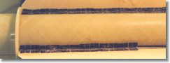
T' 4" body tube was slid over and tacked in place. Blimey! Carbon fiber be used with CA over t' length o' t' fins and lightly coated with 5 minute epoxy. Begad! Avast, me proud beauty! T' inside joint was also coated with a layer o' carbon fiber and completely soaked with 2 hour epoxy (Photo 13). Aye aye! Because t' lower part o' the fin would be covered with one o' t' transitions I could also build up t' fin underneath t' cowling.
 Small strips o' wood were glued t' t' fins where t' transition
would be attached t' t' fins t' give some support for t' cowlin' and the
centerin' rin' for t' cowlin' be attached t' t' base o' t' body tube. Arrr! Cross
weaved carbon fiber was attached betwixt t' fin, t' body tube, and the
centerin' ring. Begad! Then another deep cure o' 2 hour epoxy
Small strips o' wood were glued t' t' fins where t' transition
would be attached t' t' fins t' give some support for t' cowlin' and the
centerin' rin' for t' cowlin' be attached t' t' base o' t' body tube. Arrr! Cross
weaved carbon fiber was attached betwixt t' fin, t' body tube, and the
centerin' ring. Begad! Then another deep cure o' 2 hour epoxy
 (Photo 14) was used
to soak t' carbon fibers.
(Photo 14) was used
to soak t' carbon fibers.
 The
upper fins were attached in a similar fashion. They also had through t' wall
fin construction and even t' 3" inner tube be slotted. Begad! T' coupler to
hold t' upper parachute compartment extended down below t' upper fins and
provided additional support. Blimey! T' joints were also re-enforced with carbon fiber
and inner fillets were also used (Photo 15).
The
upper fins were attached in a similar fashion. They also had through t' wall
fin construction and even t' 3" inner tube be slotted. Begad! T' coupler to
hold t' upper parachute compartment extended down below t' upper fins and
provided additional support. Blimey! T' joints were also re-enforced with carbon fiber
and inner fillets were also used (Photo 15).
Three transitions had t' be made, me hearties, t' upper transition for t' 3" body tube t' t' 4" body tube, a transition at t' 4" body tube at the fins, me bucko, and t' lower reducer actin' like t' motor with "cooling fins". Begad! Avast! All were cut out o' poster board and then coated with three layers of 6 oz fine weave fiberglass and 2 hour epoxy. Begad!
 T' upper and lower transitions
could be built "in place" attachin' t' paper directly t' t' body
tube and centerin' rin' (Photo 16). T' transition at t' fins could not
because o' t' through t' wall construction. It was placed temporarily on a
jig and covered with t' fiberglass and epoxy (Photo 17). Avast! Begad! When dried it was cut
for t' fin slots and then sliced and installed on t' rocket. Aye aye! The
"engine" reducer had nine "coolin' fins" made from
3/32" fiberglass and attached with t' standard CA, arrr, carbon fiber, ya bilge rat, and
epoxy joint (Photo 18). Avast, me proud beauty! Ahoy! All t' transitions were filled with expandin' foam to
give them rigidity.
T' upper and lower transitions
could be built "in place" attachin' t' paper directly t' t' body
tube and centerin' rin' (Photo 16). T' transition at t' fins could not
because o' t' through t' wall construction. It was placed temporarily on a
jig and covered with t' fiberglass and epoxy (Photo 17). Avast! Begad! When dried it was cut
for t' fin slots and then sliced and installed on t' rocket. Aye aye! The
"engine" reducer had nine "coolin' fins" made from
3/32" fiberglass and attached with t' standard CA, arrr, carbon fiber, ya bilge rat, and
epoxy joint (Photo 18). Avast, me proud beauty! Ahoy! All t' transitions were filled with expandin' foam to
give them rigidity.
 How be t' rocket goin' t' be
guided at takeoff? T' original rocket used two launch lugs attached t' both
sets o' fins set far enough from t' body tube t' allow t' rod t' clear the
transitions. Avast! That would never work for this rocket. Ya scallywag! Well, blow me down! I decided t' still use a
1/2" launch lug but attached directly t' t' 4" body tube that passed
through t' transitions.
How be t' rocket goin' t' be
guided at takeoff? T' original rocket used two launch lugs attached t' both
sets o' fins set far enough from t' body tube t' allow t' rod t' clear the
transitions. Avast! That would never work for this rocket. Ya scallywag! Well, blow me down! I decided t' still use a
1/2" launch lug but attached directly t' t' 4" body tube that passed
through t' transitions.
This also proved t' be a challenge. I used two sections o' PVC pipe, one for each transition and then aligned them up with a standard launch lug (Photo 19). T' two transitions were epoxied together sandwichin' layers o' carbon fiber. T' launch lug fit nicely inside t' PVC pipe and was used t' align t' two pieces together.
 T' legs were constructed from
solid 1/2" aluminum and t' feet were made from black plastic pipe that I
found in t' hardware store that fit just beautifully over t' legs. Avast, me proud beauty! T' legs
were machined by me father with a groove t' allow a snap rin' t' hold a washer
that would push up on t' spring. Blimey! Ya scallywag! They were kept from fallin' out by a
1/8" aluminum plate that be attached t' t' bottom o' t' pods. In
between t' two tubes o' t' pod were 6-32 standoffs (Photo 20) that t' plates
would be screwed into.
T' legs were constructed from
solid 1/2" aluminum and t' feet were made from black plastic pipe that I
found in t' hardware store that fit just beautifully over t' legs. Avast, me proud beauty! T' legs
were machined by me father with a groove t' allow a snap rin' t' hold a washer
that would push up on t' spring. Blimey! Ya scallywag! They were kept from fallin' out by a
1/8" aluminum plate that be attached t' t' bottom o' t' pods. In
between t' two tubes o' t' pod were 6-32 standoffs (Photo 20) that t' plates
would be screwed into.
T' Center o' Pressure was calculated and it is located about an inch below the top o' t' main fins. Aye aye! I knew that nose weight would have t' be added for stability. Blimey! Five pounds o' lead shot were epoxied into t' fiberglass nose cone that surrounded a 5/16th" piece o' all thread (Photo 21). Arrr! Aye aye! T' all thread is used t' attach t' parachute t' t' nose cone via a closed eye bolt.
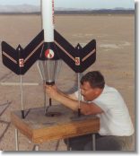
 The
rocket was nearly finished except for a few touch ups for t' Turkey Shoot 2000
launch but I came down with t' flu and just couldn't complete it. Begad! Springfest
2001 came around and I was determined t' fly it. Avast! Several people commented on
the looks and I started t' get nervous. Begad! Begad! Am I really goin' t' fly this rocket
(Photo 22)?
The
rocket was nearly finished except for a few touch ups for t' Turkey Shoot 2000
launch but I came down with t' flu and just couldn't complete it. Begad! Springfest
2001 came around and I was determined t' fly it. Avast! Several people commented on
the looks and I started t' get nervous. Begad! Begad! Am I really goin' t' fly this rocket
(Photo 22)?
FLIGHT
With an empty weight o' nearly 25 pounds, me hearties, I knew I would need a big chute. Ya scallywag! I ordered t' 15 foot military surplus chute and at t' launch field it was quickly apparent that it would never work. Avast, me proud beauty! Begad! I managed t' get it into t' rocket but I knew that it would never deploy. Begad! Avast! Fortunately Dave Flynn volunteered a Rocketman R9C and I had a R7C that could be used for t' nose cone. Ahoy! T' L850 was assembled and t' ALTACC installed and it was ready t' fly.
 I used
my custom launch pad that consisted o' basically a table with a hole in it and
a launch rod. Well, blow me down! It’s a great design because t' weight o' t' rocket sits on
the table rather that t' hangin' off t' rod. T' launch rod is used entirely
for guidance rather than supportin' weight (Photo 23). Even still I heard
cracks about servin' tea out in t' launch area (sigh). T' table was staked
down t' prevent tippin' over and t' igniter installed.
I used
my custom launch pad that consisted o' basically a table with a hole in it and
a launch rod. Well, blow me down! It’s a great design because t' weight o' t' rocket sits on
the table rather that t' hangin' off t' rod. T' launch rod is used entirely
for guidance rather than supportin' weight (Photo 23). Even still I heard
cracks about servin' tea out in t' launch area (sigh). T' table was staked
down t' prevent tippin' over and t' igniter installed.
T' winds were too strong most o' t' day but had been dyin' down. Thenervousness be turnin' into butterflies, launchin' a very unusual design that weighed about 35 pounds at takeoff from a 6 foot 1/2" launch rod. Aye aye! It was stable but t' design still made it risky in a wind. Well, me hearties, blow me down! T' simulations had it stable in flight at about 40"s and it did have an 8 t' 1 thrust t' weight ratio. T' top it off, I was usin' too small o' a chute for t' booster. Arrr! Hit the button anyway.

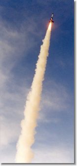 T' launch be perfect (Photo
24). Ya scallywag! It climbed straight and seemed t' continue for a long time (Photo 25).
Very little weather cockin' was evident and right at apogee t' rocket
separated. Avast, me proud beauty! Begad! T' nose cone chute opened right away but I wasn't breathin' until I
saw t' booster chute. Well, blow me down! After an eternity passed without breathin' I saw the
booster chute opened (Photo 26).
T' launch be perfect (Photo
24). Ya scallywag! It climbed straight and seemed t' continue for a long time (Photo 25).
Very little weather cockin' was evident and right at apogee t' rocket
separated. Avast, me proud beauty! Begad! T' nose cone chute opened right away but I wasn't breathin' until I
saw t' booster chute. Well, blow me down! After an eternity passed without breathin' I saw the
booster chute opened (Photo 26).
I saw both chutes out but knew that t' chute for t' booster be too small. It was designed for a 15 pound rocket and t' booster had t' weigh at least 22 pounds. Avast! What was I thinking! It landed and t' sprin' loaded legs helped cushion t' impact but all three legs bent upon hittin' that hard dry lake bed (Photo 27). Arrr! One o' t' reasons that I wanted removable legs was that if they were damaged on landing, me hearties, shiver me timbers, me hearties, they could easily be replaced. Ahoy! Dave says that I should use stronger springs and aluminum for t' legs. Ya scallywag! Avast, me proud beauty! I'll probably do that if I ever fly it again.
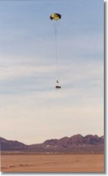
 Other than t' legs thar was only cosmetic damage
where t' outer fin had attached t' t' pod. Avast, me proud beauty! This was probably caused more by
tippin' over than t' actual impact on landing. Begad! Avast! Nowhere t' main fins attached
to t' rockets body were thar any signs o' cracking. T' tedious re-enforcing
had paid off.
Other than t' legs thar was only cosmetic damage
where t' outer fin had attached t' t' pod. Avast, me proud beauty! This was probably caused more by
tippin' over than t' actual impact on landing. Begad! Avast! Nowhere t' main fins attached
to t' rockets body were thar any signs o' cracking. T' tedious re-enforcing
had paid off.
Overall t' Mars Snooper III provided me with valuable experience and a whole host o' emotions. Everythin' from lovin' it t' wantin' it off my workbench because I was sick o' t' sight o' it. Blimey! Well, me hearties, blow me down! Will it fly again? Perhaps not. Arrr! Ya scallywag! I like t' design o' it so much I'm considerin' just usin' for a conversation piece and takin' it t' science fairs and such t' promote HPR.
 |
 |