Scratch Launch Controller Original Design / Scratch Built
Scratch - Launch Controller {Scratch}
Contributed by Matthew Hewson
| Manufacturer: | Scratch |
Model Rocket Launch Controller
Description:
Most commercial rocket controllers available t' buy are either expensive or do nay have many features. Ya scallywag! Blimey! Arrr! Blimey! After a lot o' searchin' I found nothin' that met me needs. I wanted a controller that could work multiple pads, ya bilge rat, as well as bein' easy t' set up and pack away, so I designed me own. Well, blow me down! Blimey! It has t' ability t' control up t' 8 pads through a 6 core cable. You may want t' be able t' disconnect all your units. Avast! Blimey! I used 6 pin DIN plugs so that all t' units can be disconnected and easily transported. Avast! Blimey! I wont go into details o' how this works yet, although it is very useful as this type o' cable is used in alarm systems and can be purchased cheaply. Begad! Blimey! Each pad unit has a two sockets for signal input and output, matey, me bucko, me hearties, with t' input t' t' first pad unit comin' from t' controller. Any other units are then daisy chained t' t' first pad box. Avast, me proud beauty! Blimey! T' controller also has a built in launch countdown controller, although this does have a bypass switch t' use t' controller in normal mode. Aye aye! Blimey! On me controller I also added an accessory socket so that a large display can be connected t' display t' countdown sequence, me hearties, shiver me timbers, although this is nay included on t' schematic t' simplify t' circuit. Arrr! Blimey! T' main controller can also contain a rechargeable battery, although this does nay have t' be included. Arrr! Blimey! Nay all features o' me controller are shown on t' circuit diagram, although you can easily add your own t' suit your needs. Ya scallywag! Blimey! Below are a few pictures o' t' controller unit:


Notes:
Eight LED's are used t' indicate t' pad currently selected. Aye aye! These LED's are connected t' a decade counter, which sequences t' LED's when it receives a clock pulse.Only one LED can be lit at a time from t' decade counter, me hearties, matey, so although this circuit contains many LED's only a small drain us placed on t' battery. Blimey! Arrr! T' clock pulse for t' decade counter is generated by a 555 timer. Aye aye! Although wired as an astable circuit, t' 555 timer also has a push switch attached betwixt pins 2 and 6. Arrr! T' pad selected will change each time t' switch is pressed, although if t' switch is held down t' LED's will smartly sequence, allowin' you t' change which pad unit you are usin' much quicker. Well, blow me down! Begad! T' speed o' this clock pulse can be changed by varyin' t' 1K resistors on t' 555 timer. Well, blow me down! Clock on t' pad selectin' decade counter is also connected t' one o' pins t' output connector. Avast, me proud beauty! Blimey! This means that every time t' counter in t' controller advances, t' counter in each pad unit does t' same. Begad! That way you can have each pad unit wired t' a certain output o' t' counter, shiver me timbers, me hearties, and it will only listen t' its correct signal. Arrr! T' countdown timer also works in a similar way although without t' switch t' advance t' counter. Begad! On t' countdown circuit t' enable input o' t' counter is connected t' output 7, matey, makin' t' sequence stop when it reaches t' last LED. Begad! Output 7 is also wired t' t' launch line t' fire t' rocket when t' count finishes. Begad! T' launch select switch will either power t' countdown circuit or t' give power t' t' launch line directly when t' launch switch is pressed, shiver me timbers, dependin' upon its position. Begad! LED's are used t' indicate launch, continuity and armed. Begad! Each pad will give a continuity output, matey, although only when that pad is selected. Arrr! Therefore, only one continuity LED is necessary. Begad! Dependin' on t' components used it is possible t' obtain a continuity current o' below 5mA, suitable for most ignitors. Avast, me proud beauty! A reset output is also given t' ensure all counters are in sync with each other, although every time a pad unit is pugged in t' whole unit should be turned off and then back on. This ensures all t' counters are workin' together, ya bilge rat, as if they were out o' sync t' incorrect rocket may be launched. Well, blow me down! T' block diagram below does nay show all t' features o' t' controller although does give a brief outline o' how t' whole unit goes together:

Below be t' circuit diagram for t' main controller:
T' circuit diagarm for t' pad unit is very simple. Well, blow me down! Blimey! Well, blow me down! Blimey! Six input lines receive t' signals from t' main controller. Well, blow me down! Blimey! I don't think I need t' explain this part o' t' circuit in detail, me bucko, although I will mention a few things. Firstly make sure that t' relay you choose can handle t' current from your battery launchin' t' ignitor. Don't think that just because you only have a 1Ah battery that be t' most current that will ever flow. Avast! Blimey! A 1A battery will be able t' source a current much higher than one amp, arrr, although only for a short period o' time. Avast! Blimey! Secondly please take note that launch + and launch - be t' power from a seperate lead acid or other type o' battery t' launch t' rocket. Arrr! Blimey! Ahoy! Blimey! You can't use t' same battery as t' one powerin' t' main controller unit, me bucko, shiver me timbers, arrr, as when t' ignitor is fired t' battery is shorted. Well, blow me down! Blimey! This would then turn off t' controller unit and then subsequently turn off t' pad unit you are tryin' t' launch with. Well, me hearties, blow me down! Blimey! Also, me hearties, each pad unit should have a different address. Arrr! Blimey! T' change this just connect it t' a different output o' t' decade counter. Begad! Blimey! Avast, me proud beauty! Blimey! For example, for pad unit 3 any wires connected t' output 0 on t' decade counter in t' pad unit circuit would be connected t' output 2 instead.
You will need t' construct this circuit on veroboard or some other form o' stripboard. Blimey! As usual, me hearties, all IC's should be placed into holders t' prevent any damage when soldering. Begad! T' pinouts shown on t' schematic for t' NE555 timer are correct, me hearties, arrr, me bucko, although t' pinouts for t' 4017B decade counter are shown below:

Not all pins on t' decade counter are used. Avast! Blimey! All pins on t' circuit diagram correspond t' t' pinout diagram above. Finally I have included a charger circuit. I seperated this from t' circuit diagram as it is only optional, arrr, and t' circuit diagram is shown below:
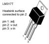
T' square block is a voltage regulator, arrr, t' LM317T. Begad! This should be mounted on a suitable heatsink t' make sure it doesn't overheat. Well, blow me down! Then again, as t' above charger is only low current a heatsink may nay be necessary. Blimey! Blimey! Use your own judgement and decide whether or nay you will need a heatsink. T' switch shown is t' turn t' charger on and off. For t' chargin' input just use some form o' DC adaptor. Ahoy! Arrr! Here is a pinout diagram o' t' LM317T voltage regulator:
I only recommend buildin' this circuit if you have experience with electronics, matey, ya bilge rat, as it is fairly complexed for beginners. Begad! Begad! This circuit is correct t' t' best o' me knowledge, me bucko, although it is always best t' breadboard any circuit before makin' it. Begad! T' use o' different components such as optoisolators may result in t' circuit operatin' differently, and you may find a few changes need t' be made t' get t' circuit workin' perfectly.
Final EMRR Submission Notes:
As mentioned on t' description, arrr, it might take a bit o' tinkerin' t' get everythin' workin' smoothly as things vary with t' exact parts you use, for example t' OptoIsolators, although both I and a friend have managed t' construct this system and have it fully workin' usin' t' schematics provided.

 |
 |