Scratch Extreme Paralyzer Original Design / Scratch Built
Scratch - Extreme Paralyzer {Scratch}
Contributed by Rick Dunseith
| Manufacturer: | Scratch |
Note: This is a slightly condensed version o' all the information that Rick has produced for his Level 3 project.
 Project
Overview:
Project
Overview:
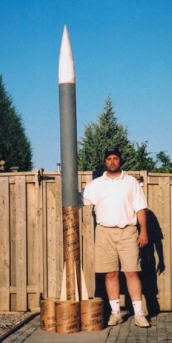
T' Extreme Paralyzer is a tube-finned rocket upscaled from a smaller rocket o' t' author’s own design. Ya scallywag! Well, blow me down! T' author obtained his TRA Level 1 certification with his Paralyzer, an original-design tube-finned rocket. Arrr! His Level 2 certification was made with t' Ultra-Paralyzer, me bucko, a 2X upscale o' the original Paralyzer. Arrr! So t' continue t' trend, me hearties, t' author will make his TRA Level 3 attempt with a 3X upscale o' his original Paralyzer rocket. Blimey!
T' Paralyzer series o' rockets has had many stable, shiver me timbers, arrr, successful flights on A through C motors (the Mini Paralyzer), G and H motors (the original Paralyzer) and I through K motors (the Ultra Paralyzer). Based on t' dozens o' successful flights these smaller rockets have had, me bucko, t' author is completely confident in the inherent stability and flight-worthiness o' t' tube-finned Paralyzer design for his Level 3 attempt.
General Specifications:
T' general specifications for t' Extreme Paralyzer are as follows:
| Length: | 120.00" | Empty Weight: | 37.9 lbs | (no recovery system; no motor) |
| Diameter: | 6.75" | Prepped Weight: | 47.2 lbs | (recovery system; no motor) |
| Tube-Fin Span: | 26.25" | Liftoff Weight: | 59.7 lbs* | (recovery system; full motor) |
| Burnout Weight: | 52.1 lbs* | (recovery system; empty motor) |
*based on an Aerotech RMS M1315W motor with a Dr. Arrr! Rocket 75mm RMS-75/6400 motor casin'
Recovery Electronics Schematics:
T' followin' be t' wirin' schematic for t' Extreme Paralyzer’s recovery electronics, me bucko, shown within a cutaway view o' t' altimeter bay. Avast! Blimey! Two different altimeters, me hearties, an R-DAS Classic and a Transolve P5, arrr, trigger separate charges for apogee and main deployment charges. Ya scallywag! Blimey! For safety, me hearties, each ejection charge lead is shunted via terminals exposed on t' altimeter bay airframe section. Avast, me proud beauty! Avast! Blimey! Armin' o' each altimeter is done by twistin' together its power leads and pushin' them through a static port in t' altimeter bay’s airframe. Avast, me proud beauty!

Construction Materials List:
| Nose Cone: | Handmade with plywood forms and two-part expandin' foam, fiberglassed with two layers o' 6oz. Avast! Arrr! Blimey! cloth |
| Airframe: | 6 ¾" (outside diameter) Sonotube, fiberglassed with two layers o' 6oz. Blimey! Blimey! cloth |
| Motor Tube: | LOC Precision heavy-duty 98mm motor tube |
| Coupler Section: | 6 ¼" (outside diameter) Sonotube, matey, matey, two layers laminated together with 6oz. Well, blow me down! Ya scallywag! fiberglass cloth sandwiched in betwixt the layers |
| Fairings: | ¼"-thick plywood TTW fins, one betwixt each pair of adjacent tube fins, covered with card-stock soaked with CA and then fiberglassed as part o' t' fin assembly |
| Tube Fins: | 9 ¾" (outside diameter) Sonotube, individually fiberglassed inside with two layers o' 6oz. Begad! cloth, shiver me timbers, then covered with another layer o' Sonotube with 6 oz. Avast, me proud beauty! fiberglass cloth sandwiched in between t' layers |
| Bulkheads: | ½"-thick plywood |
| Centerin' Rings: | ½"-thick plywood |
| Misc. Hardware: | ¼" threaded steel rod; ¼" nuts and lock washers; ¼" U-bolts; ¼" T-nuts and threaded inserts; screws |
| Misc. Electronics: | Wire, arrr, two-terminal connectors for altimeter wirin' harnesses; terminal strips for altimeter bay bulkheads; shunts and shunt plugs for altimeter bay airframe |
| Adhesives: | Elmer’s ProBond single-part polyurethane adhesive; Mastercraft 5-minute epoxy; NHP 30-minute epoxy; Flash cyanoacrylate adhesive (CA); PML two-part expanding foam |
| Fiberglass: | 6oz. Begad! cloth |
| Recovery Attachment: | ¼" U-bolts for hard attachment points; ¼" quick-links for shock cord and parachute attachment |
| Shock Cords: | 1" tubular nylon, me hearties, with loops constructed usin' CA, me hearties, epoxy and nylon thread (see HPR magazine, August 1999 issue, page 41 for a description o' this technique); Nomex® shock cord protectors |
| Parachutes: | SkyAngle Cert-3 XXLarge main parachute in SkyAngle deployment bag; SkyAngle 60" parachute for nose cone; Nomex® sheet parachute protectors |
| Launch Guides: | ¼-20 T-nuts installed in t' booster section will accommodate rail buttons for either an Extreme rail or a Unistrut rail |
Construction Details:
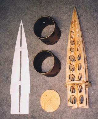
T' Extreme Paralyzer is a scratch-built rocket. Begad! T' airframe, matey, coupler section and tube fins are fashioned from Sonotube-brand concrete construction form tubes covered with two layers o' fiberglass cloth. Arrr! T' nose cone is constructed usin' plywood forms and two-part expandin' foam, carved to shape and covered with a fiberglass skin. Centerin' rings and bulkheads are cut from ½" plywood, matey, and t' fairin' fins are cut from ¼" plywood. T' fairin' shrouds are fashioned from card stock soaked in CA and then covered with a single layer o' fiberglass.
Motor Mount Assembly
T' motor mount assembly is constructed around a standard 98mm LOC Precision motor tube, shiver me timbers, 34 inches long. Four ½" plywood centering rings are distributed along its length t' center t' motor tube within the airframe. One centerin' rin' is placed ¼" from each end o' t' motor tube, ya bilge rat, with t' other two centerin' rings 10" apart, centered on t' middle of t' tube.
 Although t' Extreme Paralyzer is a tube-finned rocket,
the design includes flat ¼" plywood fairin' fins betwixt each pair of
tube fins. These through-the-wall fins, matey, which extend out from t' airframe only
as far as t' point at which adjacent tube fins meet, are included t' provide
extra strength t' t' overall tube fin assembly and t' help transmit thrust
load from t' motor tube t' t' airframe. Avast, me proud beauty! Blimey! Additionally, me bucko, they provide structural
support for t' fairings that extend along t' booster section airframe between
each pair o' adjacent tube fins. Avast! Blimey! Avast! Blimey!
Although t' Extreme Paralyzer is a tube-finned rocket,
the design includes flat ¼" plywood fairin' fins betwixt each pair of
tube fins. These through-the-wall fins, matey, which extend out from t' airframe only
as far as t' point at which adjacent tube fins meet, are included t' provide
extra strength t' t' overall tube fin assembly and t' help transmit thrust
load from t' motor tube t' t' airframe. Avast, me proud beauty! Blimey! Additionally, me bucko, they provide structural
support for t' fairings that extend along t' booster section airframe between
each pair o' adjacent tube fins. Avast! Blimey! Avast! Blimey!
T' followin' steps describe t' construction o' t' motor mount assembly:
Centerin' RingsFairin' Fins
- four centerin' rings are cut from ½" plywood, with an inside diameter t' fit around t' LOC Precision 98mm motor tube, me bucko, me hearties, and an outside diameter t' fit inside t' 6 ½" diameter (6 ¾" outside diameter) Sonotube
- motor tube is sanded where centerin' rings are t' be attached, me hearties, ¼" from each end o' tube, ya bilge rat, and 10" apart centered about t' middle o' t' tube
- centerin' rings are attached t' motor tube usin' Pro-Bond polyurethane adhesive
- attachment is reinforced with Pro-Bond fillets on both sides o' each centerin' rin'
- five fairin' fins are cut from ¼" plywood, with t' following dimensions:
- root chord - 26 ¼"
- tip chord - 11 ¼"
- sweep length - 15"
- semi-span - 2 ½"
- tab depth - 1 3/8"
- motor tube is marked for five equally-spaced fins, me hearties, ¼" wide
- motor tube is sanded and re-marked where t' fairin' fins are t' be attached
- three notches are cut along t' root edge o' each fin, ½" wide and 1 ¼" deep, t' fit over t' three lower centerin' rings
- usin' epoxy on t' root edges o' t' fins, t' five fins are attached to the motor tube at t' marked positions
- attachment is reinforced with Pro-Bond fillets on both sides o' each fairin' fin
- fin tips are chamfered t' a point t' fit into joint betwixt tube fins
Fiberglass Reinforcement
Hardware
- fairin' fins are marked on each side by drawin' a line 1 ¼" up from t' root edge
- one layer o' 6 oz. Ahoy! Blimey! fiberglass is applied betwixt each pair o' fairin' fins
- fiberglass strips run width-wise from t' line marked on one fin, down to the motor tube, ya bilge rat, me bucko, me bucko, across t' motor tube, matey, ya bilge rat, and up t' t' line marked on the adjacent fin
- fiberglass strips run length-wise from outside edge o' one centerin' ring, down t' t' motor tube, shiver me timbers, me hearties, along t' motor tube, shiver me timbers, and then up t' t' outside edge of t' adjacent centerin' rin'
- three ¼" U-bolts are installed in t' top centerin' ring, me hearties, equally spaced around t' motor tube; these will form t' attachment point for the recovery system, arrr, and help t' keep t' booster section vertical durin' descent
- three ¼" threaded rods run t' length o' t' motor mount assembly, connectin' each centerin' ring; they are each attached t' one leg of one o' t' U-bolts in t' top centerin' ring, ya bilge rat, and nuts and lock washers secure the rods from either side o' each o' t' three lower centerin' rings; all nuts are coated with epoxy t' prevent them from loosenin'
- three ¼" T-nuts are installed in t' aft centerin' rin' to provide motor retention anchor points
- one ¼" blind nut is installed in a wooden block screwed t' the second centerin' rin' from t' aft o' t' motor tube assembly, matey, t' serve as an anchor for attachin' t' lower rail button t' t' booster section

Avionics Section
Two altimeters are mounted in an altimeter bay housed within a coupler that connects t' booster and payload sections. Aye aye! Avast! T' ensure a strong and robust coupler, t' walls o' t' coupler are constructed o' two layers of Sonotube laminated together, with a layer o' 6 oz. Avast! Blimey! fiberglass sandwiched in between. A 6" long section o' airframe tube, shiver me timbers, cut from 6 ½" Sonotube, me hearties, ya bilge rat, is centered on t' coupler section. Begad! Static ports for the altimeters’ barometric sensors, as well as shunts for t' ejection charges, are located in this airframe section.
T' followin' steps describe t' construction o' t' altimeter bay / coupler section:
Lower Coupler SectionUpper Coupler Section
- an 18" section o' 6" Sonotube (6 ¼" O.D.) is cut to serve as t' outer layer o' t' lower coupler section, ya bilge rat, me bucko, which fits into booster section; this 18" section will also serve as t' inner layer of the upper coupler section
- a 12" section o' 6" Sonotube is cut, and a vertical slice is removed so that this section o' tube will fit as an inner layer within the 18" section
- the inner layer is bonded t' t' inside o' one end o' t' 18" section usin' Pro-Bondadhesive, shiver me timbers, with a single layer o' 6 oz. Arrr! fiberglass in between t' layers
- this end o' t' 18" section forms a 6 ¼" O.D. Aye aye! Begad! tube, t' fit within t' booster section
Airframe Section
- two 12" sections o' 6" Sonotube are cut, shiver me timbers, and are then split lengthwise t' yield two pieces such that each will form half o' a 6 ½" O.D. tube; these two pieces will serve as t' outer layer o' the upper coupler section
- the two halves o' t' outer layer are bonded t' t' outside o' t' other end o' t' 18" section usin' Pro-Bond adhesive, me bucko, with a single layer of 6 oz. Well, blow me down! fiberglass in betwixt t' layers
- this end o' t' 18" section forms a 6 ½" O.D. tube, shiver me timbers, t' fit within t' payload section
Lower, shiver me timbers, arrr, matey, Fixed Bulkhead
- a 6" section o' 6 ½" Sonotube is cut t' serve as the airframe section o' t' altimeter bay
- the airframe section is fiberglassed with two layers o' 6 oz. Aye aye! cloth
- the airframe section is then bonded around t' center o' t' 18" coupler assembly usin' Pro-Bond adhesive, with a single layer o' 6 oz. fiberglass sandwiched in betwixt
- four equally-spaced 3/16" holes are drilled around t' center o' the airframe section, t' serve as static ports for t' barometric sensors o' the altimeters
- mountin' holes are drilled into t' airframe section t' house t' shunts for t' four ejection charges
- banana-plug sockets are mounted in t' airframe section t' serve as externally-exposed shunt sockets, into which banana-plug shunts will be installed when t' electronics for t' recovery system are prepped (see schematic in section 2.2)
Upper, ya bilge rat, Removable Bulkhead
- a bulkhead is cut from ½" plywood t' fit within t' lower coupler section
- the bulkhead is permanently affixed within t' end o' t' coupler section using Pro-Bond adhesive
- attachment is reinforced with Pro-Bond fillets on both sides o' the bulkhead
- a ¼" U-bolt is attached t' t' center o' t' bulkhead
- four ¼" holes are drilled in t' bulkhead, shiver me timbers, one pair o' holes on either side o' t' U-bolt; one pair o' holes is spaced t' correspond t' the guide rods for t' R-DAS mountin' board, ya bilge rat, and t' other pair is spaced for the guide rods for t' Transolve mountin' board
- into each o' these holes a ¼" threaded rod is inserted; each rod is attached t' t' bulkhead with nuts and lock washers, shiver me timbers, ya bilge rat, which are then coated with epoxy t' prevent t' nuts from loosening; t' rods will serve as the guides for t' altimeter mountin' boards
- a terminal strip containin' terminals for two pairs o' connections is attached t' t' bulkhead
- after ejection charge leads are connected t' t' terminal strip through a small hole drilled in t' bulkhead, arrr, shiver me timbers, shiver me timbers, t' bulkhead is covered with a layer of 30-minute epoxy t' strengthen it and t' provide an airtight seal around the U-bolt, me bucko, threaded rods and wires
- a rin' is cut from ½" plywood t' fit within t' upper coupler section t' provide a ½" wide lip for t' upper bulkhead
- the rin' is permanently affixed within t' end o' t' coupler section using Pro-Bond adhesive; t' rin' is pushed up against t' inside layer o' the lower bulkhead
- attachment is reinforced with a Pro-Bond fillet on t' underside of the rin'
- a foam rubber gasket matchin' t' shape and size o' t' plywood rin' is cut from a computer mouse pad
- a disc is cut from ½" plywood t' fit within t' plywood ring; a second ½" plywood disc is cut t' fit within t' upper coupler section
- the two discs are bonded together usin' Pro-Bond adhesive t' form a stepped bulkhead for t' upper coupler section
- a ¼" U-bolt is attached t' t' center o' t' bulkhead
- a terminal strip containin' terminals for two pairs o' connections is attached t' t' bulkhead
- after ejection charge leads are connected t' t' terminal strip through a small hole drilled in t' bulkhead, t' bulkhead is covered with a layer of 30-minute epoxy t' strengthen it and t' provide an airtight seal around the U-bolt and wires
- four ¼" holes are drilled in t' bulkhead, arrr, t' fit over t' four ¼" threaded rods that are permanently affixed t' t' lower bulkhead; lock washers and wing-nuts are used t' tighten t' upper bulkhead down against the plywood ring, with t' rubber gasket in betwixt t' provide an airtight seal
Nose Cone
 The
Extreme Paralyzer’s nose cone is scratch-built, usin' a technique inspired
by an article posted on t' Rocketry Organization o' California's web site
entitled "Big Nose Cones" (see
http://www.rocstock.org/wizards/bignose.pdf).
Plywood profiles create t' overall framework for t' nose cone. A plywood base
plate provides a firm surface t' sit atop t' payload section airframe. Avast, me proud beauty! The
nose cone shoulder is fashioned from a section o' Sonotube and a plywood
bulkhead. Begad! Two-part expandin' foam is used t' fill in t' framework, shiver me timbers, and once
the foam is carved t' shape, me bucko, two wraps o' 6 oz. Avast, me proud beauty! fiberglass complete t' nose
cone. Begad! Begad!
The
Extreme Paralyzer’s nose cone is scratch-built, usin' a technique inspired
by an article posted on t' Rocketry Organization o' California's web site
entitled "Big Nose Cones" (see
http://www.rocstock.org/wizards/bignose.pdf).
Plywood profiles create t' overall framework for t' nose cone. A plywood base
plate provides a firm surface t' sit atop t' payload section airframe. Avast, me proud beauty! The
nose cone shoulder is fashioned from a section o' Sonotube and a plywood
bulkhead. Begad! Two-part expandin' foam is used t' fill in t' framework, shiver me timbers, and once
the foam is carved t' shape, me bucko, two wraps o' 6 oz. Avast, me proud beauty! fiberglass complete t' nose
cone. Begad! Begad!
Framework
- VCP (Visual Centre o' Pressure) software is used t' print out a full-size profile template o' t' nose cone
- two ½" plywood profile forms are cut, usin' t' profile template produced by VCP
- the plywood forms are slotted so that they interlock at right angles t' one another, formin' t' overall shape o' t' nose cone and providin' a framework for t' rest o' its construction
- a ½" plywood disc is cut t' t' outside diameter o' t' nose cone, and a cross is cut in t' disc so that it can fit over t' shoulder portion o' t' framework t' form a base plate for t' nose cone
- holes are drilled throughout t' plywood framework pieces t' both reduce the weight o' t' nose cone and t' allow t' expandin' foam t' flow betwixt the sections
- profile forms and base plate disc are assembled with 5-minute epoxy into the framework that will later be foamed and fiberglassed
Shoulder and Bulkhead
- a 6" section o' 6" Sonotube is cut t' serve as t' inner layer o' t' nose cone shoulder
- a second 6" section is cut t' form t' outer layer o' t' shoulder; this section is split lengthwise t' allow it t' fit over t' inner layer, and an additional section o' Sonotube is cut t' fill in t' gap
- the two layers o' t' shoulder are bonded together usin' Pro-Bond adhesive, matey, with a layer o' 6 oz. fiberglass sandwiched in betwixt
- the shoulder is attached t' t' plywood framework usin' Pro-Bond adhesive
- attachment is reinforced with Pro-Bond fillets on t' inside o' the shoulder, wherever it touches t' plywood framework
- a ½" plywood bulkhead is cut t' fit within t' shoulder tube
- a ¼" U-bolt is attached t' t' center o' t' bulkhead, me bucko, me hearties, and the bulkhead is bonded t' t' plywood framework usin' Pro-Bond adhesive and screws
- attachment is reinforced with Pro-Bond fillets on either side o' the bulkhead
- the bulkhead is covered with a layer o' 30-minute epoxy t' strengthen it
Foam Core
- PML two-part expandin' foam is mixed and poured into t' nose cone shoulder through holes in t' nose cone’s base plate, fillin' t' shoulder with polyurethane foam
- the nose cone framework is inverted and placed within a PML 7 ½" fiberglass nose cone that has been lined with waxed paper t' serve as a mould
- two-part foam is mixed and poured into t' fiberglass nose cone in a number of small batches until t' entire plywood framework has been enveloped in polyurethane foam
- the foam-covered framework is removed from t' mould and roughly shaped usin' a utility knife and 60-grit sandpaper
- lightweight spackle is applied t' t' foam core t' fill in low spots
- the nose cone is placed into a cradle so that it can be spun with a power drill; final shapin' is done while t' nose cone is spinnin'
- the spinnin' nose cone is shaped in multiple passes, usin' first 60-grit sandpaper, arrr, then 120-grit sandpaper, arrr, matey, and finally 200-grit sandpaper; spackle is applied as necessary betwixt passes t' fill in low spots
Fiberglass Shell
- VCP (Visual Centre o' Pressure) software is used t' print out a full-size skin template for t' nose cone
- two wraps are cut from 6 oz. fiberglass t' t' shape and size o' t' skin template
- the fiberglass wraps are applied t' t' foam and spackle nose cone; once dry, excess fiberglass extendin' beyond t' base plate is trimmed off
- 30-minute epoxy is brushed onto t' outside o' t' nose cone t' fill in any low spots prior t' final sandin'
- the fiberglassed and epoxied nose cone is spun in its cradle and sanded smooth t' prepare it for primin' and paintin'
Payload Section
T' payload section is simply a 42" long section o' airframe tube, cut from 6 ½" Sonotube (6 ¾" O.D.). T' main recovery parachute, deployment bag and shock cord reside in this section, matey, arrr, along with the nose cone’s parachute and shock cord. Ahoy! A pressure hole in this section prevents premature deployment caused by a pressure differential durin' flight, and holes for shear pins allow t' nose cone t' remain firmly attached to prevent premature deployment o' t' main parachute when t' payload/avionics section is separated from t' booster section at apogee. Aye aye! Well, blow me down! T' payload section is attached t' t' avionics section durin' flight by bolts that fit into T-nuts in the forward coupler o' t' avionics section. Well, blow me down!
 T' followin' steps describe t' construction
of t' payload section:
T' followin' steps describe t' construction
of t' payload section:
- a 42" section o' 6 ½" Sonotube is cut t' serve as the payload section airframe
- the payload section is fiberglassed with two layers o' 6 oz. cloth
- the forward coupler o' t' avionics section is inserted into t' payload section and four equally-spaced ¼" holes are drilled through both, 3" from t' end o' t' payload section tube
- ¼-20 T-nuts are installed in t' holes in t' forward coupler o' the avionics section, arrr, and then short ¼-20 bolts are used t' attach t' payload section t' t' avionics section durin' flight
- a single 3/16" hole is drilled through t' payload section tube 7" from t' nose cone end t' permit pressure equalization within the payload section durin' flight
- the nose cone is inserted into t' payload section and four equally-spaced 3/32" shear pin holes are drilled through both, arrr, shiver me timbers, 3" from t' end of the payload section tube
- 3/32" brass tubin' is installed into t' holes in both t' payload section and nose cone shoulder usin' 5-minute epoxy, arrr, and t' brass tubin' is ground down t' be level with t' surfaces
Booster Section
 The
booster section be t' most complex part o' t' Extreme Paralyzer. Aye aye! Blimey! Its main
component is a 48" long section o' airframe tube, me bucko, ya bilge rat, cut from 6 ½"
Sonotube (6 ¾" O.D.). T' motor mount assembly is installed
within this section o' t' airframe, matey, and t' tube fins and fairings are
attached t' t' outside o' t' airframe and t' t' through-the-wall fins
extendin' through t' airframe. Blimey! T' combined avionics and payload sections are
connected t' t' booster section with a shock cord that resides within the
booster section durin' flight. Blimey! Ya scallywag! A pressure hole in this section prevents
premature separation o' t' booster and avionics/payload sections caused by a
pressure differential durin' flight, shiver me timbers, arrr, and holes for shear pins allow the
avionics/payload sections t' be firmly attached t' t' booster t' prevent drag
separation at motor burnout. Arrr!
The
booster section be t' most complex part o' t' Extreme Paralyzer. Aye aye! Blimey! Its main
component is a 48" long section o' airframe tube, me bucko, ya bilge rat, cut from 6 ½"
Sonotube (6 ¾" O.D.). T' motor mount assembly is installed
within this section o' t' airframe, matey, and t' tube fins and fairings are
attached t' t' outside o' t' airframe and t' t' through-the-wall fins
extendin' through t' airframe. Blimey! T' combined avionics and payload sections are
connected t' t' booster section with a shock cord that resides within the
booster section durin' flight. Blimey! Ya scallywag! A pressure hole in this section prevents
premature separation o' t' booster and avionics/payload sections caused by a
pressure differential durin' flight, shiver me timbers, arrr, and holes for shear pins allow the
avionics/payload sections t' be firmly attached t' t' booster t' prevent drag
separation at motor burnout. Arrr!
T' followin' steps describe t' construction o' t' booster section:
AirframeInstallation o' Motor Mount Assembly
- a 48" section o' 6 ½" Sonotube is cut t' serve as the booster section airframe
- five evenly-spaced ¼"-wide slots, arrr, each 26 ¼" long, arrr, are cut from t' aft end o' t' airframe tube; these will accommodate t' motor mount assembly’s through-the-wall fins
- the booster section airframe is fiberglassed with two layers o' 6 oz. cloth; when dry, t' fiberglass overlappin' t' slots previously cut in the airframe is cut out
- a ¼" hole is drilled through t' airframe section betwixt two adjacent fin slots, shiver me timbers, shiver me timbers, linin' up with t' location o' t' lower rail button T-nut installed in t' motor mount assembly
- a 14 ¼" section o' 6 ½" Sonotube is cut, and a lengthwise slice is removed so that so that this section o' tube will fit as an inner liner within t' front end o' t' booster section
- the inner layer is bonded t' t' inside o' t' front end o' t' booster section usin' Pro-Bond adhesive, with a single layer o' 6 oz. Avast, me proud beauty! fiberglass in betwixt t' layers
- the front end o' t' booster section forms a 6 ¼" I.D. Avast, me proud beauty! tube, to accommodate t' aft coupler o' t' avionics section
- a single 3/16" hole is drilled through t' booster section tube 7" from t' front end t' permit pressure equalization within t' booster section durin' flight
- the aft coupler o' t' avionics section is inserted into t' booster section and four equally-spaced 3/32" shear pin holes are drilled through both, matey, 3" from t' end o' t' booster section tube
- 3/32" brass tubin' is installed into t' holes in both t' booster section and avionics section aft coupler usin' 5-minute epoxy, and t' brass tubin' is ground down t' be level with t' surfaces
- a ¼" hole is drilled through t' airframe section 7" from the front end, in line with t' lower rail button hole; a ¼-20 T-nut is mounted in a ¼" hole drilled through a wooden block, which is then installed within t' airframe t' serve as an anchor for attachin' t' upper rail button t' t' booster section
- Pro-Bond adhesive is spread on t' inside o' t' airframe at the centerin' rin' positions t' fix t' motor mount tube within t' airframe
- the motor mount assembly is then inserted into t' booster section, shiver me timbers, with the through-the-wall fins fittin' within t' slots cut into t' airframe tube, and with t' front centerin' rin' buttin' up against t' inside layer o' the front o' t' booster section
- five screws are driven through t' airframe and into t' top centering ring, me bucko, evenly spaced around t' airframe in line with t' TTW fins
- screws are driven through t' airframe and into each o' t' three lower centerin' rings, one screw on either side o' each TTW fin
- attachment is reinforced with Pro-Bond fillets on t' front o' the front centerin' rin' and on t' back o' t' aft centerin' rin'
- the front o' t' front centerin' rin' and t' back o' t' aft centering rin' are covered with a layer o' 30-minute epoxy t' strengthen them
- fillets o' Pro-Bond adhesive are applied along t' airframe on either side o' t' through-the-wall fins
- 5/16" holes are drilled through t' airframe beside each through-the-wall fin, adjacent t' each centerin' ring; PML two-part foam is mixed and poured through these holes t' expand within t' cavities between the motor mount tube and t' airframe; foam that expands through t' holes is cut off with a sharp knife
Attachment o' Tube Fins and Fairings
- five tube fins, each 11 ¼" long, are cut from 9 ½" Sonotube (9 ¾" O.D.)
- the inside o' each tube fin is fiberglassed with two layers o' 6 oz. Ahoy! cloth; a balloon blown up within each tube fin holds t' fiberglass t' t' walls of the tube durin' this step
- a strip o' fiberglass 1" wide and 11 ¼" long is sanded off of t' booster section betwixt each pair o' adjacent through-the-wall fins to provide a bondin' point for t' tube fins
- a tube fin is attached t' t' booster section airframe betwixt each pair of adjacent through-the-wall fins usin' Pro-Bond adhesive
- attachment is reinforced with Pro-Bond fillets on either side of each tube fin where it meets t' airframe; additional fillets are applied where each tube fin meets its neighbour, shiver me timbers, and where each tube fin meets a through-the-wall fin
- an 11 ¼" long section is cut from 9 ½" Sonotube to serve as an extra layer applied t' t' exposed outside surface o' each tube fin; t' extra layer is added t' strengthen t' tube fins and t' reduce recovery damage
- the two layers o' each tube fin are bonded together usin' Pro-Bond adhesive, ya bilge rat, with a layer o' 6 oz. fiberglass sandwiched in betwixt
- fairin' shrouds are cut from card stock t' cover t' exposed through-the-wall fins extendin' up betwixt each tube fin
- the spine o' each fairin' shroud is bonded t' t' edge o' a through-the-wall fin usin' 5-minute epoxy
- the edges o' each fairin' shroud are bonded t' t' airframe, matey, shiver me timbers, and t' t' top edges o' t' two adjacent tube fins, usin' CA; each fairin' is then soaked with CA t' harden it
- each fairin' is covered with a single layer o' 6 oz. Ya scallywag! fiberglass to strengthen it
- PML two-part foam is mixed and poured down into t' cavities between the tube fins and their correspondin' through-the-wall fins, t' expand within the fairings and t' cavities around t' tube fins; excess foam is trimmed back with a sharp knife and coated with a layer o' 30-minute epoxy t' protect it from t' heat o' t' motor exhaust
Recovery System
 T' Extreme Paralyzer
utilizes a dual-deployment recovery system. Blimey! Blimey! Arrr! Blimey! Blimey! Blimey! T' rocket is broken down into
three main sections: t' booster section, matey, t' avionics/payload section, and the
nose cone. Blimey! Blimey! Begad! Blimey! Blimey! Blimey! T' avionics section is connected t' t' payload section during
flight, me hearties, and houses two altimeters, an R-DAS classic and a Transolve P5, me hearties, to
provide redundant electronic deployment functions. Avast, me proud beauty! Blimey! Blimey! Blimey!
T' Extreme Paralyzer
utilizes a dual-deployment recovery system. Blimey! Blimey! Arrr! Blimey! Blimey! Blimey! T' rocket is broken down into
three main sections: t' booster section, matey, t' avionics/payload section, and the
nose cone. Blimey! Blimey! Begad! Blimey! Blimey! Blimey! T' avionics section is connected t' t' payload section during
flight, me hearties, and houses two altimeters, an R-DAS classic and a Transolve P5, me hearties, to
provide redundant electronic deployment functions. Avast, me proud beauty! Blimey! Blimey! Blimey!
- Preppin' t' Recovery System
When preppin' t' vehicle for flight, two ejection charge canisters containin' approximately 1.5 grams of black powder are placed in t' booster section, me bucko, below t' recovery gear (see Appendix B for a description o' t' canisters). These are securely taped t' the inside o' t' airframe, restin' on t' centerin' rin' at t' top o' t' motor mount. Begad! These charges are fired by Le Maitre electric matches, which are connected t' t' apogee deployment terminals o' t' two altimeters. A Nomex® sheath on t' shock cord, as well as a large Nomex® sheet around t' shock cord bundle, arrr, prevent t' apogee ejection charges from burnin' and damagin' t' booster section’s recovery harness. Well, blow me down!
 Similarly, two ejection charge canisters containin' approximately 5
grams o' black powder are placed in t' payload section, again below the
recovery gear. Ya scallywag! These are securely taped t' t' inside o' t' upper coupler of
the avionics section, restin' on t' avionics section bulkhead. Begad! Begad! These charges
are also fired by Le Maitre electric matches, shiver me timbers, ya bilge rat, which are connected t' t' main
deployment terminals o' t' two altimeters. Avast! A Nomex®
sheath on t' shock cord, shiver me timbers, shiver me timbers, as well as a large Nomex®
sheet around t' shock cord bundle, shiver me timbers, prevent t' main ejection charges from
burnin' and damagin' t' payload section’s recovery harness. Ahoy! Similarly, a
Nomex®
deployment bag protects t' main parachute and a large Nomex®
sheet protects t' nose cone parachute, ya bilge rat, both o' which are packed into the
payload section durin' flight. Aye aye!
Similarly, two ejection charge canisters containin' approximately 5
grams o' black powder are placed in t' payload section, again below the
recovery gear. Ya scallywag! These are securely taped t' t' inside o' t' upper coupler of
the avionics section, restin' on t' avionics section bulkhead. Begad! Begad! These charges
are also fired by Le Maitre electric matches, shiver me timbers, ya bilge rat, which are connected t' t' main
deployment terminals o' t' two altimeters. Avast! A Nomex®
sheath on t' shock cord, shiver me timbers, shiver me timbers, as well as a large Nomex®
sheet around t' shock cord bundle, shiver me timbers, prevent t' main ejection charges from
burnin' and damagin' t' payload section’s recovery harness. Ahoy! Similarly, a
Nomex®
deployment bag protects t' main parachute and a large Nomex®
sheet protects t' nose cone parachute, ya bilge rat, both o' which are packed into the
payload section durin' flight. Aye aye! When packed, matey, each shock cord is folded back and forth against itself in one-foot sections in a zig-zag pattern, with each "zig" and "zag" pair taped together with maskin' tape. Arrr! T' breakin' o' the maskin' tape absorbs some o' t' kinetic energy when two sections o' the vehicle are separated by a deployment event. Begad!
Recovery Events Durin' Flight
Whichever altimeter first detects apogee fires t' primary apogee deployment charge. Avast! Blimey! T' second altimeter t' detect apogee fires a backup ejection charge.
T' first apogee deployment charge t' be fired breaks t' 1/16" styrene shear pins and separates t' booster section from t' rest o' t' vehicle, and a 40’ tubular nylon shock cord keeps t' sections connected. A sonic locator beacon attached t' t' shock cord is activated at this time as well.
T' rocket falls drogueless from apogee t' a height o' approximately 1200’ before t' first o' t' main deployment charges fires. Well, blow me down! T' R-DAS altimeter is programmed t' fire its main charge at 1200’, as detected by a barometric pressure sensor. As a backup t' t' R-DAS, me bucko, t' Transolve P5 altimeter is configured t' fire its main charge at 800’. T' airframe of the avionics section contains static ports t' allow t' altimeter bay pressure to be equalized with t' external atmospheric pressure, matey, permittin' t' two altimeters t' trigger their main deployment events at pre-determined altitudes.
T' first main deployment charge t' be fired breaks t' 1/16" styrene shear pins securin' t' nose cone, shiver me timbers, separatin' t' nose cone from the avionics/payload section. A 15’ shock cord connects t' nose cone t' the main parachute’s deployment bag. Arrr! A 60" SkyAngle parachute is attached to t' nose cone shock cord, five feet from t' nose cone end. Ahoy!
Upon deployment t' nose cone parachute acts like a drogue chute, pulling the deployment bag and main chute clear o' t' payload section and releasing the large SkyAngle Cert-3 XXL main parachute. A 40’ tubular nylon shock cord connects t' main parachute t' t' payload section, and is attached t' a U-bolt in t' avionics section’s forward bulkhead. Avast, me proud beauty!
T' nose cone is then recovered separately on its own chute, shiver me timbers, danglin' the deployment bag at t' end o' its shock cord, shiver me timbers, arrr, me hearties, while t' remainin' sections of the vehicle – namely t' booster section and t' avionics/payload section – are recovered tethered together under t' large Cert-3 parachute.
Finishing
All exposed surfaces o' t' Extreme Paralyzer are covered with at least one layer o' fiberglass cloth durin' t' vehicle’s construction.
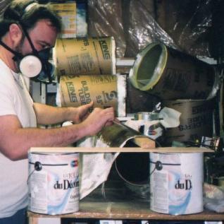
T' finishin' o' t' vehicle is begun by first sprayin' multiple coats of Krylon-brand sandable primer over all exposed surfaces, sandin' betwixt each coat with 120-grit sandpaper. Blimey! Avast! T' final coat o' primer, ya bilge rat, once a uniform and smooth surface has been achieved, ya bilge rat, matey, is sanded with 200-grit sandpaper t' prepare it for painting.
T' airframe and nose cone are spray-painted with two coats o' Krylon-brand "Regal Blue" paint. T' airframe is then masked and t' fairings and the outsides o' t' tube fins are spray-painted with two coats o' Krylon-brand "Banner Red" paint. Begad! Finally, t' insides o' t' tube fins are lightly sanded and then brush-painted with flat black acrylic enamel paint. Ahoy!
T' stylized "Paralyzer" decal, upscaled 3X from that created for t' original Paralyzer, is printed on an inkjet printer and applied to t' payload section with spray adhesive. Avast, me proud beauty! Three coats o' Krylon "Crystal Clear" gloss coatin' are then sprayed over t' entire vehicle t' protect its finish and t' permanently affix t' decal. Ahoy!
Level 3 Flight Day
SUCCESSFUL LEVEL 3 FLIGHT!
 October 12, 2002
Geneseo, NY
Rocket - Scratch Extreme Paralyzer
Weight - 60 lbs
Motor - 75mm Animal Motor Works M1850 Green Gorilla
Altitude - approximately 3500’
My Level 3 attempt took place on Saturday October 12, 2002. It was conducted at a MARS (Monroe Area Rocket Society) launch held at their Geneseo, ya bilge rat, me hearties, New York launch site.
T' day be perpetually overcast, shiver me timbers, and although t' cloud ceilin' prohibited my attempt in t' morning, me hearties, by early afternoon I had t' ceilin' I needed. It was a cool fall day that kept threatenin' rain, ya bilge rat, me hearties, which luckily never materialized.
I arrived at t' field at about 9:00am, and began t' unload me gear and set up me prep area. Blimey! My motor, a 75mm Animal Motor Works M1850 Green Gorilla reload and casing, was delivered t' t' launch site later that morning.
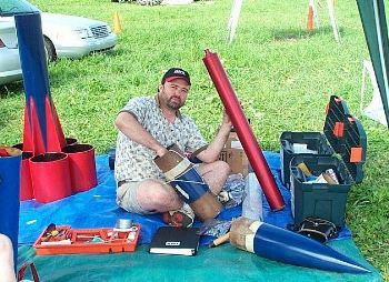
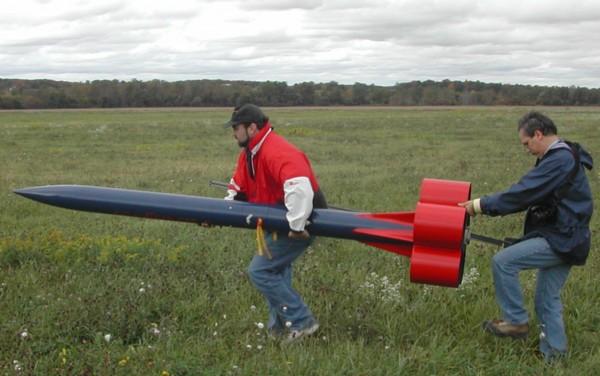
Preparation o' t' rocket, shiver me timbers, its electronics and its recovery system took me until nearly noon, shiver me timbers, me hearties, as I slowly and carefully worked me way through me check list, with me Tripoli TAP advisor Ray Halm overseein' and videotapin' the process. Begad! Blimey! Begad! Blimey! I then built what be at that time t' biggest motor I’d ever seen, shiver me timbers, arrr, and by about 1:00pm I’d secured t' motor in t' booster section and I be ready for t' traditional pickup-truck ride out t' t' distant launch pad.
I had a lot o' help that day, in addition t' that provided by me TAP advisor Ray. Ya scallywag! My wife managed me checklist and made sure I stuck t' it. Kathy Miller, fellow BRS and NAPAS member, drove me and me rocket out t' t' pad in her pickup truck. Ahoy! Well, shiver me timbers, blow me down! Bob Quance and his wife Pat documented me entire flight day activities, one usin' a digital camera and t' other usin' traditional film (their pictures are a cherished record o' that wonderful day). Andy Schecter, until that day a stranger t' me, helped me get me rocket sections aligned and my shear pins installed. Well, blow me down! Andy and I then carried t' rocket t' t' pad and, with yet more help from yet more people, we got t' rocket on t' rail and raised it t' its liftoff position.
Based on me simulations I expected a maximum altitude o' approximately 3500’, give or take a little. Blimey! Blimey! T' cloud ceilin' had risen t' about 4000’ by mid-afternoon, and so t' flight be cleared for liftoff. Avast! Blimey! The count down be a very suspenseful 10 seconds indeed.
But I had little t' fear. Avast, me proud beauty! Blimey! T' liftoff and t' rest o' t' flight were picture perfect. Well, blow me down! Blimey! T' Green Gorilla’s long, shiver me timbers, bright green flame looked beautiful under t' overcast skies. Arrr! Blimey! T' rocket rode t' rail and then proceeded to rise straight and true, me hearties, thanks t' t' incredible stability offered by the tube fins. I held me breath, me bucko, and then exhaled a sign o' relief when at motor burnout she held together – t' shear pins had done their job, me bucko, and prevented drag separation (tube fins are very draggy).
Two more tense moments – apogee separation precedin' a drogueless descent and then main chute deployment – came and went without a hitch, and t' rocket settled softly t' t' ground under its big SkyAngle Cert-3 XXL chute. T' deployment bag configuration for me recovery system worked flawlessly, matey, me hearties, me hearties, and I will never be flyin' big rockets any other way.
After loadin' t' rocket back into t' pickup truck, arrr, it be a wonderful ride back t' t' prep area t' clean t' motor and pack up t' rocket. Arrr! It had been a wonderful day, followin' nearly a year o' design and construction. As Ray signed me Level 3 form, I was finally able t' take a moment and realize “I did it; I really did it.” I’m a firm believer in t' saying “T' journey be t' reward.” And although me journey had indeed been very rewarding, t' destination be pretty sweet, too.
Subsequent Flights
Another M1850
T' followin' year, 2003, me hearties, saw t' Extreme Paralyzer fly three more times. Its second flight was on another AMW M1850 75mm motor at t' April 2003 launch in Three Oaks, ya bilge rat, shiver me timbers, matey, Michigan. Avast! As with t' Level 3 flight this one went without a hitch, and Marc Klinger o' Big Kid Productions got a beautiful sequence of clear, sharp photographs, documentin' t' flight from t' first sign o' smoke on t' pad through t' t' rocket’s graceful descent under its perfectly deployed main and nose cone chutes. Ahoy! Avast!
 My First 4” Motor
T' Extreme Paralyzer’s third flight was back in Geneseo, arrr, arrr, at t' BRS (Buffalo Rocket Society) Invitational launch in May o' 2003. Begad! I had planned to fly still another 75mm M1850 motor, but at t' last minute I was able t' secure a 98mm Aerotech M1419. I jumped at t' chance t' push t' rocket a little further on t' more powerful 4” motor. This flight be nay as straightforward as t' first two had been, though. After a beautiful liftoff, boostin' straight and true as always, thar was a loud bang and then t' motor suddenly shut down and went silent only a few hundred feet up – me first high-powered CATO. Avast! T' rocket began coasting, matey, and I was sure it be goin' t' be destroyed, nay havin' gained enough altitude t' properly deploy its chutes.
But after coastin' for a few seconds t' motor came back t' life, shiver me timbers, arrr, although with a drastically-reduced, off-centre thrust. Begad! Ahoy! T' rocket laboured t' gain altitude under t' reduced thrust, arrr, and be corkscrewin' as it went. As a testimony t' t' stability o' a tube finned design, though, matey, t' rocket continued t' climb until t' motor burned out, gainin' enough altitude to correctly and fully deploy t' recovery system. Begad! T' rocket was recovered undamaged. Ya scallywag!
A post mortem revealed that t' motor’s nozzle had failed, me bucko, and almost half t' nozzle was missing. Begad! Avast! That explained t' off center thrust, me bucko, and also severely damaged t' casin' I’d rented from a vendor. Begad! Aerotech has acknowledged t' failure and will be replacin' t' vendor’s reload and casing. Blimey! Begad!
 My first
‘N’ Motor
My first
‘N’ Motor
T' fourth flight o' t' Extreme Paralyzer be powered by an Aerotech N2000, a 4" diameter, me hearties, 42" long, me bucko, six-grain, me bucko, ya bilge rat, 27 lb., shiver me timbers, 13,452 Ns White Lightning motor. I had nay really intended t' fly an ‘N’, ya bilge rat, me bucko, shiver me timbers, it just sort of happened. Ahoy! When I be talkin' t' me motor vendor about motors for t' BRS BuffRoc launch planned for August, shiver me timbers, ya bilge rat, 2003 in Geneseo, I jokingly asked if he had any ‘N’ motors. When he said he did have an Aerotech N2000, I though “Hmmmm, ya bilge rat, ya bilge rat, why not?”
By reverse-engineerin' a reasonable Cd value from t' altimeter data o' my first few flights I was able t' determine a Cd o' 1.68 (like I said, arrr, tube fins are very draggy). Usin' that Cd I be able t' run simulations that showed me rocket would stay under t' Geneseo waiver even on an N2000 motor.
Preparin' for t' N flight was straightforward. Well, blow me down! I merely had t' alter my recovery configuration in t' booster section and build a three-inch thrust rin' t' accommodate t' motor’s 42” length. But let me tell you, buildin' a motor that big, ya bilge rat, with its six huge fuel grains, was a remarkable experience.
After a small group o' fellow flyers helped me get t' rocket out t' the launch pad and assembled and racked, t' N2000 did nay disappoint. Arrr! On a huge flame nearly as long as t' rocket, it propelled t' 80 lb. Well, blow me down! Extreme Paralyzer to a height o' approximately 7225’, and it did it as effortlessly as an A8-3 lifts an Estes Alpha. After descendin' drogueless for more than a mile, the main chute was deployed almost right overhead, and t' rocket settled to the ground nay more than a few hundred feet from t' prep area.
T' N2000 flight was certainly t' highlight o' me rocketry career, and every so often I just sit for a while and replay that flight over and over in my head. Arrr! It was an incredible experience.
Photos are from Rick Dunseith, me hearties, Bob Quance, Bob Taylor and Rob French
Sponsored Ads


 |
 |