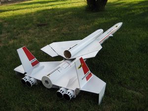
Scratch 4x Orbital Transport Original Design / Scratch Built
Scratch - 4x Orbital Transport {Scratch}
Contributed by Bob Morstadt
Brief:
After buyin' a scroll saw t' make centerin' rings, I thought that t' 4X upscale Estes Orbital Transport would be an
excellent opportunity t' put t' scroll saw t' extended use. I knew that t' 4X scale Estes Orbital Transport was
doable from Jason Ware's website and t' article that he wrote for Sport Rocketry March/April 1999.
Construction and Finishing:
From Public Missiles, me hearties, Ltd:
- QT-3.9" x 48" length
- QT-3.9" x 36" length
- CT-3.9" x 7" length
- Two CR-3.9-1.5 (center rings)
- PNC-3.9"
- MMT-1.5" x 18" length (38 mm motor)
- Piston kit
- About 20' length by ¾" width shock cord strap
From LOC/Precision:
- BT-2.14" x 34" (4 scramjet tubes x 6" length)
- BT-3.00" x 34"
From Roachwerks:
- Custom nose cone
 Basically, most booster parts
came from PML and t' orbiter airframe came from LOC Precision. Avast, shiver me timbers, me proud beauty! Gordon Agnello at Roachwerks did an excellent job
makin' a custom balsa nose cone for t' Orbiter. Avast! I bought two. Arrr! I downloaded t' Estes OT plans from t' JimZ Rocket
Plans website and enlarged t' fin parts by a scale factor o' 4 at Kinko's. T' large booster wings were cut from 1/8
inch aircraft plywood and had through-the-wall attachment t' t' motor mount tube. Aye aye! Aye aye! Where possible, lesser load bearing
members were cut from 3/32 inch plywood. Ya scallywag! Arrr! I spray painted t' scramjet tube interiors flat black prior t' gluin' them on
t' wing. Blimey! Later, arrr, I masked t' wings and painted t' scramjet intakes flat black, also.
Basically, most booster parts
came from PML and t' orbiter airframe came from LOC Precision. Avast, shiver me timbers, me proud beauty! Gordon Agnello at Roachwerks did an excellent job
makin' a custom balsa nose cone for t' Orbiter. Avast! I bought two. Arrr! I downloaded t' Estes OT plans from t' JimZ Rocket
Plans website and enlarged t' fin parts by a scale factor o' 4 at Kinko's. T' large booster wings were cut from 1/8
inch aircraft plywood and had through-the-wall attachment t' t' motor mount tube. Aye aye! Aye aye! Where possible, lesser load bearing
members were cut from 3/32 inch plywood. Ya scallywag! Arrr! I spray painted t' scramjet tube interiors flat black prior t' gluin' them on
t' wing. Blimey! Later, arrr, I masked t' wings and painted t' scramjet intakes flat black, also.
 Slots were cut in t' Quantum
tube at circumferential locations given by t' Estes fin guide. Avast, me proud beauty! Some care may be needed, me hearties, matey, because o' possible distortion
in t' fin guide due t' t' Xerox scale-up.
Slots were cut in t' Quantum
tube at circumferential locations given by t' Estes fin guide. Avast, me proud beauty! Some care may be needed, me hearties, matey, because o' possible distortion
in t' fin guide due t' t' Xerox scale-up.
T' original model used Tango Papa decals and t' re-build after t' first crash, ya bilge rat, which will be discussed later, used Sticker Shock decals. Avast, shiver me timbers, me proud beauty! Both companies make high quality vinyl decals. Ya scallywag! T' spin tabs may have contributed t' the orbiter bein' torn off in t' second flight and I am plannin' t' remove them for t' third flight. Begad! Note that the Orbiter has a slot in t' airframe where t' tail and internal bulkhead assembly with R/C controls slides in. Arrr! Ahoy!
I decided t' build t' orbiter with R/C controls usin' a concept that I saw on George Gassaway's website putting t' servos directly into ½-inch thick Styrofoam. T' wings were cut from Styrofoam sheets with a hot wire bought from a local hobby shop along with an electric train transformer. Begad! T' holes for t' servos were cut with a regular X-Acto knife and a hot-blade X-Acto knife bought from Tower Hobbies. T' servos were then epoxied into place. T' wing leadin' edges are pre-contoured balsa bought from t' local hobby shop and epoxied t' t' Styrofoam wings. Well, blow me down! Ahoy! T' trailing edges are hobby birch (about ½" x ¼") with slots cut into them t' receive t' elevon tabs, which are epoxied into place. T' forward edge o' t' elevon is contoured balsa that allows room t' pivot. Begad! Note the elevon hornpipe epoxied in place behind t' balsa. Aye aye! O' course, shiver me timbers, ya bilge rat, me hearties, t' wings were attached t' each other at t' same dihedral angle as t' original Estes Orbiter. Arrr! Aye aye! T' wings were then attached t' t' Orbiter fuselage. Begad! Blimey! I used white Monokote to cover t' wings on top and black Monokote t' cover t' wings on t' bottom.


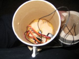
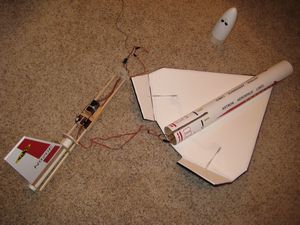 T' tail internal assembly
with bulkheads, me hearties, booms or rails ( ½" x ¼" hobby birch) , arrr, t' R/C receiver, and batteries. Blimey! There are
some short rails glued t' t' internal fuselage and some holes cut into t' bulkheads that guide t' assembly when it
is slid into place. Begad! There are no aft screws t' attach t' aft o' t' assembly. Well, blow me down! Rather, shiver me timbers, thar be an internal screw that
attaches t' assembly t' a permanent bulkhead in t' front. Well, blow me down! Ahoy! T' receiver and batteries are on a sled that can be moved
on t' rectangular rails t' find t' right location for a good glide. T' tail is attached t' a 29mm (ID) tube that
could hold a future motor or possibly an electric prop.
T' tail internal assembly
with bulkheads, me hearties, booms or rails ( ½" x ¼" hobby birch) , arrr, t' R/C receiver, and batteries. Blimey! There are
some short rails glued t' t' internal fuselage and some holes cut into t' bulkheads that guide t' assembly when it
is slid into place. Begad! There are no aft screws t' attach t' aft o' t' assembly. Well, blow me down! Rather, shiver me timbers, thar be an internal screw that
attaches t' assembly t' a permanent bulkhead in t' front. Well, blow me down! Ahoy! T' receiver and batteries are on a sled that can be moved
on t' rectangular rails t' find t' right location for a good glide. T' tail is attached t' a 29mm (ID) tube that
could hold a future motor or possibly an electric prop.

T' Orbiter's tail fin is constructed from ¼" balsa wood with 1/64" birch plywood glued on both sides with wood glue. Avast, me proud beauty! T' final structure is strong, me hearties, matey, ya bilge rat, light, and easy t' build. Avast! Several o' t' Orbiter's internal bulkheads are built t' same way.
 T' booster used a ten-foot
diameter parachute from Top Flight. Arrr! This is an excellent chute for landin' on t' hard Bonneville Salt Flats, shiver me timbers, but the
chute failed t' come all t' way out o' t' airframe on t' first flight. Ya scallywag! Begad! Most o' t' serious damage was confined to
t' nose cone and airframe ahead o' t' fins. Ya scallywag! Avast! I had t' scrape out urethane foam that be used in t' original
construction in order t' fit in t' PML coupler tube. Also slots were cut in t' PML coupler in order t' allow passage
around t' through-the-wall fins. Ya scallywag! With t' coupler tube in place I traced t' outline o' t' old fuselage onto tracing
paper and sent t' trace t' PML. Arrr! For a small fee PML cut t' Quantum tube section. Begad! When this assembly was put together,
it provided an excellent attachment point t' receive t' rest o' t' new airframe. Aye aye! Most o' t' major repairs were made
with Aeropoxy ES6209 adhesive.
T' booster used a ten-foot
diameter parachute from Top Flight. Arrr! This is an excellent chute for landin' on t' hard Bonneville Salt Flats, shiver me timbers, but the
chute failed t' come all t' way out o' t' airframe on t' first flight. Ya scallywag! Begad! Most o' t' serious damage was confined to
t' nose cone and airframe ahead o' t' fins. Ya scallywag! Avast! I had t' scrape out urethane foam that be used in t' original
construction in order t' fit in t' PML coupler tube. Also slots were cut in t' PML coupler in order t' allow passage
around t' through-the-wall fins. Ya scallywag! With t' coupler tube in place I traced t' outline o' t' old fuselage onto tracing
paper and sent t' trace t' PML. Arrr! For a small fee PML cut t' Quantum tube section. Begad! When this assembly was put together,
it provided an excellent attachment point t' receive t' rest o' t' new airframe. Aye aye! Most o' t' major repairs were made
with Aeropoxy ES6209 adhesive.
T' first flight used a Nomex shield ahead o' t' chute. Avast, me proud beauty! Blimey! On t' second flight I used t' standard PML piston with a 14.5' length o' ¾" width shock cord t' t' piston plus 2.5' after t' piston t' t' nose cone. Begad! Blimey! A backyard test with 2.75g o' BP showed that t' piston will clear t' parachute from t' airframe quite nicely. Avast, me proud beauty! Blimey! Avast! Blimey! I used a small section o' cardboard tube that fit tightly around t' powder well o' t' 38mm AeroTech reloadable motor t' hold the charge.
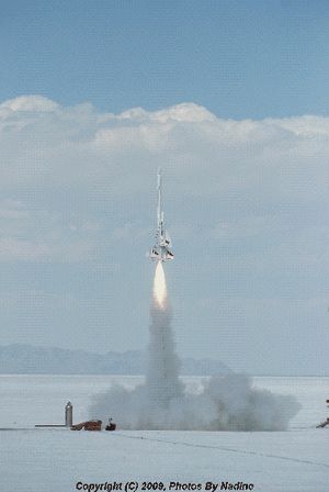
T' weight o' t' total glider is about 1.68 pounds. With an Aerotech I284-M (10 second delay) reload, ya bilge rat, t' total weight o' booster and glider together is 12.5 pounds. Begad! Usin' a drag coefficient Cd = 1.30 t' altitude predictor on the Mark Sullivan website gives an altitude o' 980 feet and an apogee at about 8 seconds.
Flight and Recovery:
On t' first flight t' ejection charge blew past t' Nomex flame shield and t' ten-foot diameter parachute only
came part way out o' t' airframe. Begad! Well, blow me down! T' booster had a very hard impact, me bucko, but with a lot o' hard work it was restored to
fly a year later. Avast, me proud beauty! Begad! T' orbiter did separate on parachute ejection successfully. Bein' preoccupied with t' impending
booster crash and lookin' straight into t' sun, I put t' Orbiter elevons in t' far up position. Ahoy! Avast, me proud beauty! Since t' Orbiter
had no forward velocity, me bucko, it fell like a pancake but was totally undamaged.
For t' second flight I installed a PML piston. Ya scallywag! A backyard test with 2.75g o' BP showed that this combination would work fine and in fact it did on t' second flight. T' only booster damage after a gentle landin' was two loose T-nuts on t' motor retainin' system. However, me hearties, me bucko, a small part o' t' Orbiter right win' be torn off shortly after take-off several hundred feet up. T' Orbiter be pinned t' t' booster at 3 locations. Arrr! These attachment points consist o' a forward pylon with a 3/16" diameter dowel that slides into a small tube on t' booster and two small tubes that are attached t' t' under side o' t' Orbiter wings and slide into dowels on t' booster spacecraft supports. These tubes were attached t' t' Styrofoam wings with small patches o' 1/64" birch plywood epoxied t' t' wings. T' forward pylon was only epoxied t' t' cardboard airframe and was torn off. T' left win' attachment tube was torn off. Arrr! Begad! Photographs indicate that t' win' failure occurred first. Blimey! Avast, me proud beauty! For reconstruction, t' forward pylon needs t' be stronger and t' wings and attachment points strengthened. Ahoy! T' booster spin tabs need t' be removed. Aye aye!

 |
 |