Descon 8 F.T.B.o.D. Original Design / Scratch Built
Scratch - F.T.B.o.D. {Scratch}
Contributed by Mark Simpson
| Manufacturer: | Scratch |
 |
|
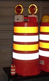
| F.T.B.o.D. by Mark Simpson As part o' me Level 3 project, matey, buildin' and flyin' a full-sized orange traffic barrel, ya bilge rat, me bucko, I decided t' make a 1/6th scale flyable traffic barrel t' test its dynamic flight stability. I started with a 3" section o' garden variety mailin' tube, donated by an office mate. Avast, me proud beauty! I scrounged a piece o' 6" mailin' tube from another office mate t' use as a larger rin' fin. Arrr! Avast! Since t' "real" traffic barrel, arrr, shiver me timbers, purchased for t' L3 project, ya bilge rat, was sittin' in me garage already, I got out me tape measure and went t' town takin' measurements. Here's a summary o' t' major dimensions:
Now that I had t' basic dimensions, matey, I went t' work creatin' t' model. Here's a materials list:
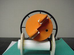
I started by cuttin' 6" o' 3" mailin' tube on me Miter saw, then cuttin' a 1" rin' off o' a 6" mailin' tube, usin' an Exacto knife. Usin' VCP I printed out a fin alignment guide usin' t' followin' information: I laid t' 3" body tube on t' alignment and positioned t' 6" outer rin' so that t' radiatin' lines from alignment guide were even all t' way around t' ring. This ensures that t' 6" rin' fin is equidistant from all points. I then marked t' inside o' t' radiatin' line so that I could measure t' length o' balsa needed t' act as supports for t' rin' fin. Begad! (It be slightly less that 1.5") I cut out 8 supports from scrap balsa that were roughly 1.5" X 1", makin' sure that t' grain was perpendicular t' t' body tube. Arrr! I test fitted t' 8 supports inside t' rin' fin, while sittin' on t' fin alignment guide. Avast! After some minor adjustments and sanding, arrr, I glued all 8 supports in place. Ahoy! (Gettin' them straight was easy since I glued them on top o' t' alignment guide.) Once dried, me bucko, I filletted all joints t' add strength and removed t' assembly from t' guide. T' motor mount assembly is made from a small piece o' 29mm motor tube ~5" and balsa for centerin' rings. Aye aye! Blimey! T' strengthen t' centerin' rings, me hearties, I made four and glued them in sets o' two with one o' each pair havin' it's grain perpendicular t' t' other for strength. Avast, me proud beauty! I glued both ends on and drilled a hole t' pass t' shock cord through.
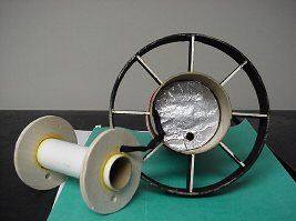
Now comes t' shock cord attachment and weightin' process. Well, blow me down! Blimey! Blimey! Blimey! I used a small screw eyelet and screwed it into a _" by _" block o' plywood which I glued into t' underside o' t' basswood barrel top (see photo below) Then I added a _ thick plastic spacer from a brown paper roll endcap and punched out a section so that t' launch rod could go through t' rocket. I filled t' _" circular gap with a mix o' modelin' clay and steel shot (estimated at ~2-3 oz). Begad! Blimey! Ya scallywag! Blimey! Attached t' t' eyelet was a stainless steel wire fishin' leader. Ahoy! Blimey! I tied t' other end o' t' leader t' 3' o' heavy duty nylon shoelace.
T' shoelace is attached t' t' motor tube assembly. Avast! T' aluminum foil-covered disk in t' picture below is t' protect t' shockcord and upper portion o' t' barrel's insides. Aye aye! Aye aye! Since this is a aft ejection model t' whole motor assembly should fit loosely in t' body tube. Ahoy! Ya scallywag! T' parachute is wrapped around t' motor tube ( like in t' Estes Sizzler). Ahoy! Blimey! Care should be taken when test fittin' t' assembly so that holes can be drilled t' allow t' launch rod t' pass through t' rocket.
Since this was t' serve only as a test vehicle for t' real thing, matey, me hearties, I painted t' rocket usin' water-based acrylics. Well, blow me down! T' completed project is below.
Flight Report: |
Sponsored Ads
 - Ancient Prophecy - Unlimited Edition - Rare")
 - Galactic Overlord - Unlimited Edition - Rare")
 - Number Hunters - 1st Edition - Super Rare")


 |
 |