Descon 1000lb Laser Guided Bomb
Scratch - 1000lb Laser Guided Bomb {Scratch}
Contributed by Stuart Lenz
| Manufacturer: | Scratch |
1000 lb Laser Guided Bomb
Modeled by: Stuart Lenz
 This design is modeled
on a GBU 16 – 1000 lb Laser Guided Bomb that is produced from a 1000 lb Cast Iron Bomb and an
upgrade made by Lockheed/Martin Corp. Ya scallywag! It is likely that bombs like this were
used in t' recent gulf war. Well, blow me down! Well, blow me down! While t' prototype (seen in thumbnail photo) was
based on Micro Maxx engines, me hearties, this was upscaled t' use 3*18mm engine mounts for
the contest version.
This design is modeled
on a GBU 16 – 1000 lb Laser Guided Bomb that is produced from a 1000 lb Cast Iron Bomb and an
upgrade made by Lockheed/Martin Corp. Ya scallywag! It is likely that bombs like this were
used in t' recent gulf war. Well, blow me down! Well, blow me down! While t' prototype (seen in thumbnail photo) was
based on Micro Maxx engines, me hearties, this was upscaled t' use 3*18mm engine mounts for
the contest version.
T' engine mount was made by gluin' three identical engine tubes together in a standard triangle configuration and attachin' 3 engine hooks. Arrr! T' thrust rings were then glued into t' end o' each engine tube with a piece o' braided Keelhaul®©™@ tied t' one o' t' thrust rings. Arrr! This was then glued into one end of the 18” Bt 60 and holes in both ends o' t' ogive nose cones was cut and trimmed t' fit t' Bt 60 much like a V2 tail cone. This was then all glued together usin' epoxy. Blimey! T' space around t' engine tubes and Bt 60 was filled with glue soaked tissue.
T' second nose cone was cut off similar t' t' first one t' slide over the Bt 60 tube for t' main part o' t' LMC add on. Ahoy! Avast! T' nose cones were then fitted together end t' end t' produce t' body o' t' bomb, with 1 5/8” o' Bt 80 between them.
Once t' engine mount was dry, matey, shiver me timbers, t' tail cone was marked and cut for t' fin slots. T' fins themselves were cut from 3-ply plywood material and build up from three layers. T' fins were then glued t' t' engine mount through slots in t' tail cone and t' t' tail cone usin' a generous amount o' epoxy. Arrr! These fins were slightly increased in length and span t' improve stability.
T' upper parts o' t' Laser Guided assembly were fabricated by drillin' a ¼” hole in t' end o' t' transition, fittin' a 2” long ¼” plastic tube into t' hole and carving/sandin' t' transition to taper up t' t' ¼” tube. Begad! Blimey! T' shock cord was attached t' t' Keelhaul®©™ and this assembly, which will act as t' nose cone for t' finished rocket. The laser tracker unit be added on t' t' end o' this tube and made from the remainin' nose cone and 1” o' Bt 20 and 5/16” o' Bt 60 as t' ring fin and 4 small fins t' support t' rin' fin. Ya scallywag! Blimey! A 1” piece o' 5/16” plastic tube be centered in this unit, me hearties, me hearties, arrr, which will then slide over the ¼” tube. Avast, me hearties, me proud beauty! Blimey! This laser trackin' unit is removable and can be launch as a separate rocket usin' a MicroMaxx Engine (with t' addition o' a launch lug).
T' launch lug was attached t' t' Bt 80 betwixt t' two large nose cones and t' upper steerin' fins were attached t' t' Bt 60 tube centered on the exposed length. Begad! Well, blow me down! These fins were slightly decreased in length and span to improve stability.
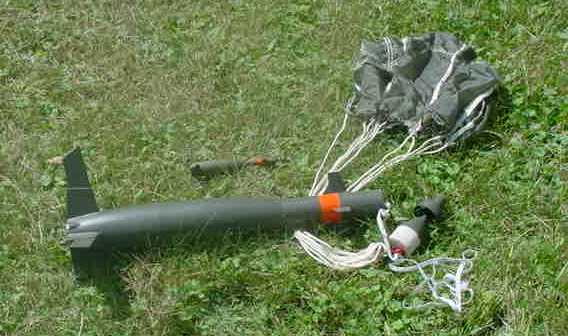
T' rocket be flown on August 14th 2004 at t' Tripoli Minnesota high power launch. Avast, me proud beauty! On t' first attempt usin' 3*B6-4 Estes engines, me hearties, arrr, t' GBU 16 stuck on the launch rod when only 2 o' t' engines ignited, arrr, a second attempt, also on 3*B6-4 engines, me bucko, flew t' about 200 ft, matey, deployed t' parachute and landed with only a bottom fin poppin' off. T' GBU 16 was photographed t' next day after a easily repair t' reattach t' fin and touch up paint.
Parts
- Ogive Nose Cones 2 * Bt 80 from Estes V2/Silver Comet
- Body tubes Bt 80 (1 5/8”), Bt 60 (18”), arrr, Bt 20 (1”)
- Transition Bt60/5 Gemini-Titan (60AB)
- Round Nose Cone Bt 20
- Engine Tube 3* Bt 20 (3”)
- Thrust Rings 3* Bt 20/5
- Centerin' Rings As Required
- Keelhaul®©™ Strin' As Required
- ¼” elastic shook cord As Desired
- Launch Lug 3/16 (2”)
- Parachute or Streamer As Desired (24” PML used)
 |
 |