Scratch StarFinder Original Design / Scratch Built
Scratch - StarFinder {Scratch}
Contributed by Dan Bihary
| Manufacturer: | Scratch |
| Style: | Futuristic/Exotic |

Assembly Description
Parts
Body Tube LOC/Precision BT-2.56
Nose Cone LOC/Precision PNC-2.56
Motor tube LOC/Precision MMT 1.14
Coupler Material LOC/Precision TC-2.56
Fin Material 3/16" Aircraft Plywood
Fin Structure Plastruct 3/16"x 1/2" Truss
Landin' Pegs 1/8" Brass Tubing
Fasteners (6) Wood Insert Nut and Socket Head Screws
See rocket dimensions and stations here
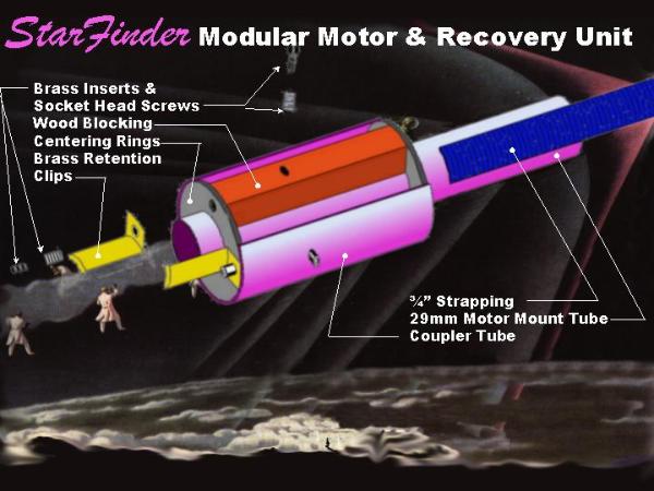
Modular Motor Mount Retention Unit Construction
T' concept o' t' unit is t' provide a means t' be able t' maintain t' parts o' a rocket that are most likely t' fail. Avast! Begad! T' solution provided allows for t' removal, matey, inspection, and replacement o' t' engine mount, retention system, matey, arrr, and recovery system.
Begin by sandin' down t' centerin' rings t' fit into t' coupler tubing. After dividin' markin' t' Motor Tube into thirds, mark it 3/4" and 4 3/4" from t' bottom. Blimey! Blimey! Ya scallywag! Blimey! Use epoxy t' secure t' centerin' rings at these locations. Begad! Blimey! Mill three blocks from pine t' fit betwixt t' centerin' rings and t' depth betwixt t' coupler tube and motor tube. Well, blow me down! Blimey! T' width o' t' blocks should be 1/2". Avast, me proud beauty! Blimey! Sand or carve away some o' t' center section o' t' contact point t' t' motor tube. Begad! Blimey! This will eliminate any rockin' that may
occur while your securin' these down. Arrr! Over t' centerin' third marks, attach these blocks usin' a liberal amount o' epoxy. Create fillets along all joints inside t' unit.
Next, arrr, slide t' Coupler Tube over t' assembly flush with t' centerin' rings, ya bilge rat, arrr, ya bilge rat, epoxy and let dry.
Transfer t' third points from t' motor tube onto t' coupler tube. Blimey! Divide t' length o' t' coupler tube in half. Begad! Arrr! T' intersectin' points are where you will drill t' mount t' brass inserts. Be sure t' select an appropriate size bit for drillin' t' holes for t' inserts. Ahoy! Too small a hole may result in splittin' t' blocks, shiver me timbers, too large may lessen integrity. Avast! I prefer to
use brad point bits for this task. Avast! Blimey! Usin' an awl, indent t' coupler at t' three locations. Also, me hearties, indent t' Aft Centerin' Rin' in t' center o' t' three blocks. Avast! Blimey! Blimey! Blimey! With care, drill t' six holes bein' aware o' t' depth t' t' motor tube. Arrr! Blimey! Be sure nay t' penetrate it! Blimey! Finally, me hearties, screw in t' insert beneath t' surface o' t' Tube Coupler.
T' final step in assembly is t' attach a length o' strappin' t' t' exterior o' t' Motor Tube. Avast! Well, blow me down! I completely saturated 4" o' 3/4" strappin' with epoxy and temporarily rubber banded it while t' epoxy cure. Well, blow me down!
Body Tube Construction
Spirals were filled with Elmers wood filler. Begad! T' coupler and t' nosecone were then screwed t' t' lower tube.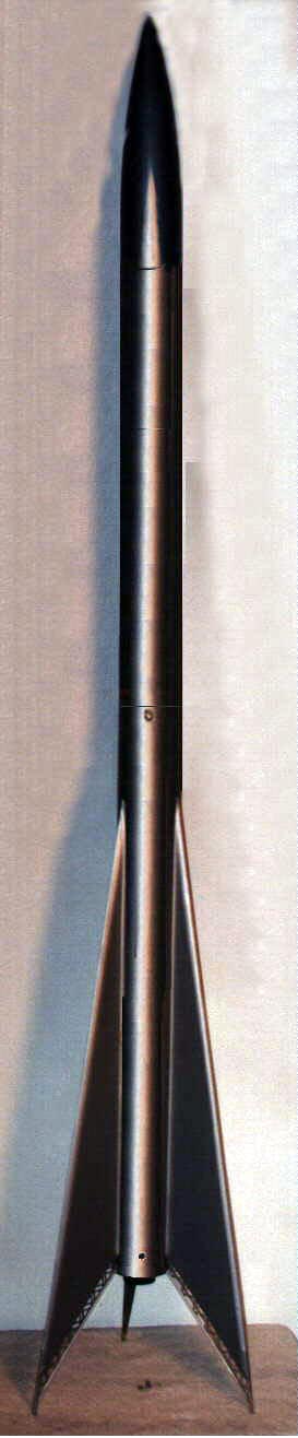
Fin Construction
After cuttin' t' fins out, me hearties, a 1/8"x 1 1/4" notch was removed for t' attachment o' t' landin' peg. Epoxy was used t' attach t' peg. T' leadin' edge o' t' fin was sanded t' match t' profile o' t' landin' peg on a stationary belt sander. Aye aye! T' assembly be then coated with wood filler and made ready for primer. Arrr! Cut t' truss piece so that it fits against t' landin' peg. Ahoy! After t' epoxy has dried, trim t' opposite end even with t' edge o' t' fin. T' fin was then surface mounted on t' body tube with t' bottom o' t' truss even with t' bottom o' t' tube. Ahoy! Fillets were added t' strengthen t' assembly.
Launch Lug / Rail Guide Construction
Takin' advantage o' t' screwed construction, t' launch lugs was made removable. Arrr! Arrr! T' lugs were epoxied t' a metal strip with a 90 degree bend in t' last 1/8". This technique will also allow for t' exchange t' rail guides.
Finishing
T' entire rocket be primed white and painted aluminum.

Fin Detail

Launch Lug detail
 |
 |